Networking Basics
This section will cover some of the basic concepts regarding network infrastructures and general tips for installations.
Common Networking Terminology
Main Distribution Facility
The main distribution facility (MDF) is the primary distribution point for all infrastructure cabling. All intermediate distribution facilities (IDF) are typically cabled directly back to the MDF using fiber cables. The MDF is positioned in the same location where core switching, routing, servers and other devices are located.
Intermediate Distribution Facility
The intermediate distribution facilities (IDF) is where endpoint cabling is terminated and patched into edge switching and other devices.

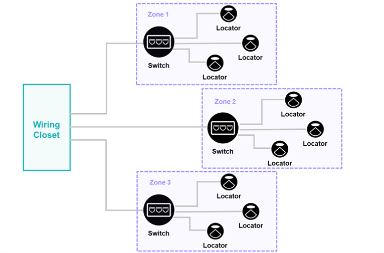
Zone Cabling
Zone cabling is an extended star networking topology, where several endpoint connections terminate and are patched to a switch or other device that requires a single connection back to an IDF or MDF. Zone cabling can dramatically lower the cost of a cabling infrastructure based on the environment and overall number of cable drops by negating the necessity for long runs back to an IDF or MDF from an area with a high concentration of network connected devices.

Dynamic Hosting Configuration Protocol
A network management protocol used on UDP/IP networks where a Dynamic Hosting Configuration Protocol (DHCP) server dynamically assigns an IP address and other network configuration parameters to devices on a network so that they can communicate with other devices on that network.
Virtual Local Area Network
Virtual Local Area Networks (VLAN) create the appearance and functionality of network traffic that is physically on a single network but acts as if it is split between separate networks. VLAN's keep network traffic separate without requiring multiple sets of cabling and network devices, such as switches and routers.
Cabling Tips
-
All cabling (including patch cables, jacks and plugs) used for connectivity of devices in the Quuppa system should be at least UTP Cat-5e.
- Ensure that any and all switches deployed within the infrastructure have the
power overhead to accommodate all PoE devices to be connected to the switch,
not just the Locators. If multiple PoE device types are connected to a
switch, other devices may use more of the available PoE budget and not leave
enough overhead to accommodate the addition of Locators.Note: Each Locator consumes about 1W.
-
It is advisable to leave a service loop (a coil of Ethernet cable, typically secured near the end termination of a device) for any possible future needs to relocate a device within a short distance or for re-terminations.

-
No cabling run should exceed 100m, to include any service loops, cross-connects, and/or patch cables.

-
All cabling connections should be checked using a cable tester, such as the Fluke MicroScanner 2, which can acquire and troubleshoot cable length, the wiremap, cable IDs and the distance to the fault.

- All fiber uplinks should be checked using a fiber tester, such as the Fluke
Pro Optical Fiber Tester.

- Ensure all connections at Locators, switches, patch panels etc are properly terminated and firmly connected.
